
Applicable Products
| Part number | Description |
| QUARTZ-GOLD-GW21(485)-LTE4 (EU) | An LTE Cat 4 router with dual built in Gigabit Ethernet ports. |
Completion time
The outlined steps are anticipated to require approximately 15 to 20 minutes for completion.
Introduction
RS-485 is a standard for serial communication that is widely used in industrial and commercial applications. It is known for its robustness in noisy environments, long-distance capabilities, and support for multiple devices on a single bus. This application note aims to explain the basics of RS-485 and provide a practical example of how to implement RS-485 communication with a QUARTZ GOLD router.
Requirements:
• QUARTZ-GOLD-GW21(485)
• RS-485 device (in the case of this app note a SHT20 Temperature Humidity Sensor)
• DC power supply
• Ethernet Cable
• A Modbus master simulator
What is RS-485?
RS-485, also known as TIA-485(-A), is a differential serial communication standard. It is designed to support high-speed data transmission over long distances and through electrically noisy environments. Unlike RS-232, which uses single-ended signalling, RS-485 uses differential signalling, making it more immune to noise.
Key Differences
RS-485 and RS-232 are both standards for serial communication, but they have significant differences in terms of signalling, performance, and applications.
RS-485:
• Differential Signalling: Uses two wires (A and B) for each signal, where the data is transmitted as the voltage difference between these lines.
• Multi-Drop Capability: Supports multiple devices on the same bus (up to 32 devices or more with repeaters).
• Long Distance: Capable of transmitting data over distances up to 1200 meters.
• Voltage Levels: Operates with lower voltage levels, typically between -7V to +12V, with a differential voltage of ±1.5V minimum.
RS-232:
• Single-Ended Signalling: Uses a single wire for each signal relative to a common ground. This makes it more susceptible to noise over long distances.
• Point-to-Point: Typically supports a single transmitter and receiver, making it suitable for direct communication between two devices.
• Short Distance: Typically limited to distances of about 15 meters (50 feet).
• Voltage Levels: Uses higher voltage levels, typically between ±3V to ±15V for signalling.
How RS-485 Works
In most cases, RS-485 communication follows a master-slave architecture. The master acts as the transmitter, sending requests to designated slave devices, which function as receivers. Each slave device continuously monitors the network for queries specifically addressed to it. Upon receiving a query, a slave device will either perform the requested action or send a response back to the master. A slave device does not initiate communication on its own.
Data is transmitted as a differential signal over two wires. When the voltage on line A is higher than on line B, it represents a logic high and vice versa. All devices communicate over a shared bus, with each device being assigned a unique ID.
Procedure
Hardware Setup
• Wiring: Connect the A and B lines of your device to the corresponding RX/A and TX/B ports on the QUARTZ-GOLD.
• Power: Ensure all devices share a common ground and are properly powered. The sensor used in this example operates within a voltage range of 9-36V while the QUARTZ-GOLD uses 7.5V to 32V dc. The 12V DC power supply provided with the QUARTZ-GOLD is suitable for powering both the router and sensor.
• Connectivity: Connect one end of an Ethernet cable to the WAN/LAN port on the QUARTZ-GOLD and the other end to an RJ45/Ethernet port on your computer.
QUARTZ Setup
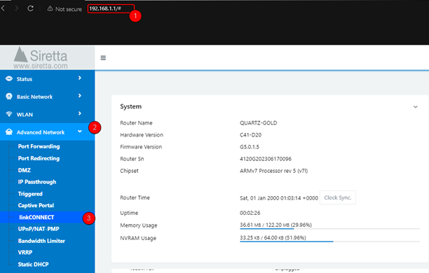
• Access the interface: Open a web browser and navigate to 192.168.1.1. When prompted, enter the login credentials located on the unit.
• From the home page, click on ‘Advanced network’, then select ‘linkCONNECT’ from the dropdown menu.
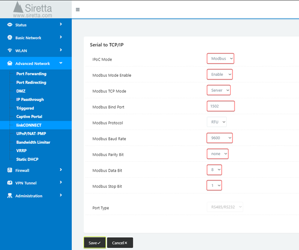
• You will need to modify some settings on this page.
– First set the IPoC mode to Modbus – this is the communication protocol being used.
– Set Modbus Mode Enable to Enable.
– Set Modbus TCP Mode to Server.
– Set the Modbus Bind Port to your desired port number.
– Change the Modbus Baud Rate to match that of the RS-485 device being used, in this case 9600.
– Adjust the Modbus Parity, Data, and Stop Bits to match the settings of the RS-485 device used. In this case none, 8 and 1 respectively.
– Click ‘Save’ once complete. (Some router services will be restarted)
Software Setup
In order to communicate with any slave devices you will need to download and install a Modbus master application.
A Modbus master application is essential for managing and interacting with Modbus slave devices, providing the necessary interface to control and monitor devices. You can use software like Modbus Poll, Modscan, or any other Modbus master application for this purpose.
The master sends requests to slave devices, which then respond with the requested information or perform the specified actions. Alternatively, a microcontroller or PLC (e.g., Arduino) can serve as the Modbus master.
Siretta has tried and tested the following master software:
• ModbusMaster
Installation
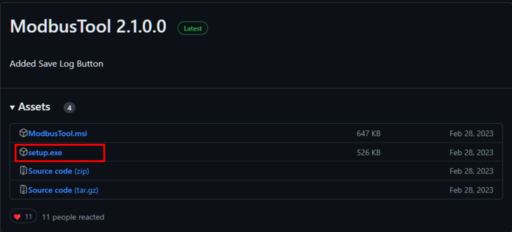
Click on one of the hyper-links to download the Modbus master application. Follow the installation wizard to correctly configure the software.
1. ModbusMaster
Using Modbus Master
Software/Device Configuration
• Open the Modbus software.
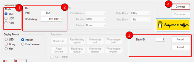
• Select ‘TCP’ under communication mode – This defines the communication protocol to use.
The primary difference between Modbus TCP and Modbus RTU lies in their communication media and application scenarios. Modbus TCP is mainly used for network communication, making it ideal for long-distance communication. In contrast, Modbus RTU is for serial communication, which is suited for short-distance communication between devices. Modbus UDP, uses the User Datagram Protocol, is faster and requires less bandwidth than Modbus TCP/IP, but it is less reliable because it does not guarantee packet delivery or correct sequencing.
• Input the same port number previously assigned to the router and the IP address ‘192.168.1.1’.
• Find the Sensor’s Modbus Address. The sensor should have a specific Modbus address (also called a slave ID). This information can generally be found in the sensor’s documentation/datasheet. In the case of the SHT20 used in this example, the Modbus address is ‘0x01’ or ‘1’
• Click ‘Connect’
The communication log window will report either a successful or unsuccessful connection. If the connection is unsuccessful, check the TCP settings and retry.

Reading data from connected device
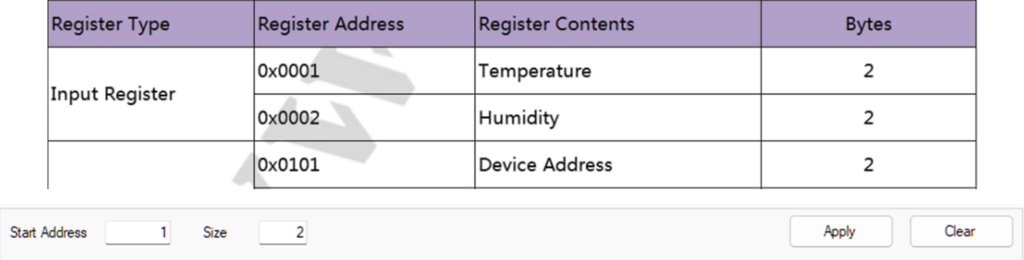
In Modbus communication, ‘registers’ are 16-bit data storage locations used to hold information. Each register has a specific address and a defined size. The main types of Modbus registers include:
Coils: Binary output data (read/write)
Discrete inputs: Binary input data (read-only)
Input registers: Analogue input data (read-only)
Holding registers: General-purpose storage for analogue output data (read/write)
Function codes are used to query these registers, eliciting a response with the requested information.
• First, specify the starting register address and the number of registers to read. This information is typically provided in the device’s documentation.
• Click ‘Apply’. Please note that we are following the SHT20 example, your registers may differ.
• Select the preferred display format, this will change how the data is presented.
• Click on the ‘Read input register’ function.
• Observe the communication log for a confirmation of a successful read.

Interpreting received data
Slave devices can be visualised as having an internal spread sheet populated with numbers. The Modbus master requests data from a specific cell (identified by a row and column) in this spreadsheet, and the slave responds with the corresponding data. In this analogy, the ‘columns’ represent the register types, and the ‘rows’ represent the register numbers.
The data from the sensor will be displayed in the spreadsheet section. Interpret any data according to the device’s documentation.
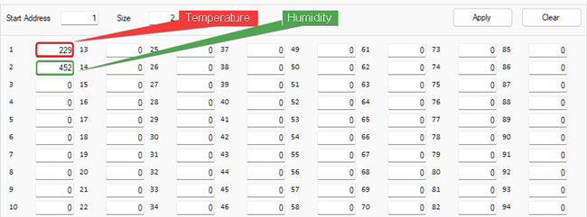
In reference to the SHT20 sensor’s documentation, the readings correspond to a temperature of 22.9°C and a relative humidity of 45.2% RH.
By following the guidelines and example provided in this application note, you can effectively integrate RS-485 communication into your projects/applications.
Additional reading/Useful links
| Description | Author |
| QUARTZ-GOLD Hardware Manual | Siretta |
| QUARTZ-GOLD Software Manual | Siretta |
| Modbus 101 | Control solutions Minnesota |
| Modbus Poll Download | Modbus tools |
| Modscan64 | Wintech |
| ModbusMaster | Graham Ross |
